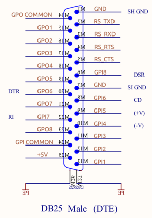
RS232 and GPIO Connector
From SOUND4wiki
The RS232 port can be used to feed the SOUND4 device with RDS UECP commands.
Only the RXD/TXD signals are used for UECP, there is no handshaking : the CTS/RTS are not used
Connector
| Pin | Function | Direction |
|---|---|---|
| 1 | GND | Ground |
| 2 | RS_TXD | Out |
| 3 | RS_RXD | In |
| 4 | RS_RTS | Out |
| 5 | RS_CTS | In |
| 6 | GPI8 | Opto isolated Input |
| 7 | GND | Ground |
| 8 | GPI6 | Opto isolated Input |
| 9 | GPI5 | Opto isolated Input |
| 10 | GPI4 | Opto isolated Input |
| 11 | GPI3 | Opto isolated Input |
| 12 | GPI2 | Opto isolated Input |
| 13 | GPI1 | Opto isolated Input |
| 14 | GPOCOM | Common GPO rail |
| 15 | GPO1 | Solid State Relay |
| 16 | GPO2 | Solid State Relay |
| 17 | GPO3 | Solid State Relay |
| 18 | GPO4 | Solid State Relay |
| 19 | GPO5 | Solid State Relay |
| 20 | GPO6 | Solid State Relay |
| 21 | GPO7 | Solid State Relay |
| 22 | GPI7 | Opto isolated Input |
| 23 | GPO8 | Solid State Relay |
| 24 | GPICOM | Common GPI High-side rail |
| 25 | GP5V | +5V (Out), Fuse protected (100mA) |
RS232
The DB25-M GPIO+RS232 is compatible with the V.24 standard, "DTE" side, meaning that it's the same as a computer-side connector.
Consequently when connecting a computer to the SOUND4 device, you have to use a Null Modem (cross cable).
So if your PC COM is male SUBD-9, the connection must be at minimum :
- PC COM DB9M TXD (pin 3) must go to (pin 3) DB25M RS_RXD
- PC COM DB9M RXD (pin 2) must go to (pin 2) DB25M RS_TXD
- PC COM DB9M GND (pin 5) must go to (pin 1) DB25M GND
(see Null_modem wiring diagram)
(Optionally other V24 signals can be connected (CTS, RTS, CD, DSR, DTR) so a fully wired branded Null-Modem cable or adapter should work)
Notes :
- the RS232 output voltage is approx. ±6V. Full ±12V is accepted at input.
- the output RS_TXD pin is not active (so is 0V instead of +6V) until there is activity on RS_RXD pin.
