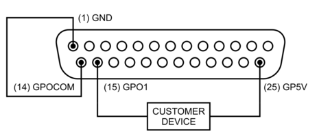
RS232 and GPIO Connector
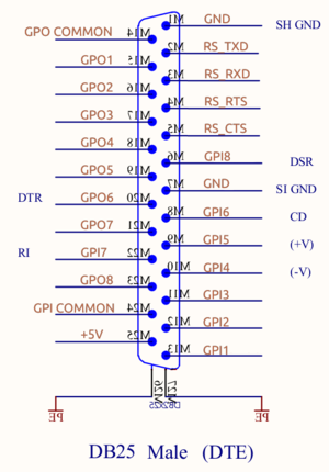
The male DB25 connector is used for both RS232 and GPIO, providing 8 General Purpose Inputs and 8 General Purpose Outputs.
Connector
| Pin | Function | Direction |
|---|---|---|
| 1 | GND | Ground |
| 2 | RS_TXD | Out |
| 3 | RS_RXD | In |
| 4 | RS_RTS | Out |
| 5 | RS_CTS | In |
| 6 | GPI8 | Opto isolated Input |
| 7 | GND | Ground |
| 8 | GPI6 | Opto isolated Input |
| 9 | GPI5 | Opto isolated Input |
| 10 | GPI4 | Opto isolated Input |
| 11 | GPI3 | Opto isolated Input |
| 12 | GPI2 | Opto isolated Input |
| 13 | GPI1 | Opto isolated Input |
| 14 | GPOCOM | Common GPO rail |
| 15 | GPO1 | Solid State Relay |
| 16 | GPO2 | Solid State Relay |
| 17 | GPO3 | Solid State Relay |
| 18 | GPO4 | Solid State Relay |
| 19 | GPO5 | Solid State Relay |
| 20 | GPO6 | Solid State Relay |
| 21 | GPO7 | Solid State Relay |
| 22 | GPI7 | Opto isolated Input |
| 23 | GPO8 | Solid State Relay |
| 24 | GPICOM | Common GPI High-side rail |
| 25 | GP5V | +5V (Out), Fuse protected (100mA) |
RS232
The RS232 port is mainly used to feed the SOUND4 device with RDS UECP commands.
The DB25-Male GPIO+RS232 connector is compatible with the V.24 standard, "DTE" side, meaning that it's the same as a computer-side connector. Consequently when connecting a computer to the SOUND4 device, you have to use a Null Modem (cross cable).
Only the RXD/TXD signals are used for UECP, there is no handshaking : the CTS/RTS are not used
So if your PC COM is male SUBD-9, the connection must be at minimum :
- PC COM DB9M TXD (pin 3) must go to (pin 3) DB25M RS_RXD
- PC COM DB9M RXD (pin 2) must go to (pin 2) DB25M RS_TXD
- PC COM DB9M GND (pin 5) must go to (pin 1) DB25M GND
(see Null_modem wiring diagram)
(Optionally other V24 signals can be connected (CTS, RTS, CD, DSR, DTR) so a fully wired branded Null-Modem cable or adapter should work)
Notes :
- the RS232 output voltage is approx. ±6V. Full ±12V is accepted at input.
- the output RS_TXD pin is not active (so is 0V instead of +6V) until there is activity on RS_RXD pin.
- A validated cable reference is : https://fr.rs-online.com/web/p/products/1828825/
Using GPI
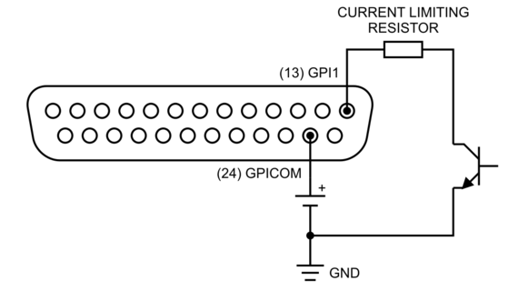
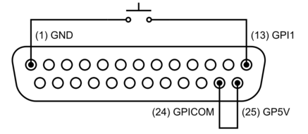
To activate one Input, GPI pin would be pulled to ground , with a voltage applied on the GPICOM pin (Common to all GPI).
Using external power supply is the recommended method in order to avoid possible ground loops between equipment, as shown in Figure 1-1. The maximum allowed external power supply for logic control is 48 volts DC.
NOTE the presence of Current Limiting Resistors per GPI pin. The intention is to limit the current to 20mA for each GPI pin. Use the table below to choose the suitable Resistor’s value.
If the equipment being controlled is electrically isolated, then the use of the GPIO port’s power supply is acceptable.
CAUTION: The use of current limiting resistor per GPI pin is required for some voltages, see table (each input has an internal 330ohms protection).
NOT PROTECTING THE GPI COULD DAMAGE YOUR DEVICE.
| VDC | External Resitor |
|---|---|
| 5 | 0 |
| 6 | 0 |
| 12 | 680 / 0.25 Watt |
| 24 | 1.8k / 0.5 Watt |
| 48 | 3.9k / 1 Watt |
Using GPO
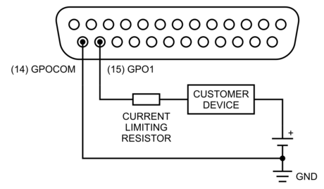
The GPO portion of the GPIO port are Solid State Relays. Current should be limited to 100 mA per GPO pin of a port. Maximum allowed voltage is 48 volts. The following diagram shows the recommended connections for outputs with the use of an external power supply.
If necessary, a Current Limiting Resistors must be used to limit the current to 100mA for each GPO pin.
NOT PROTECTING THE GPO COULD DAMAGE YOUR DEVICE.
If the device being controlled is electrically isolated, than the internal GP5V supply can be used, maintaining a 100mA limit on current drawn.
NOTE: GPO pins and GPOCOM are not polarized, current can flow both directions.
Internal connections of the GPIO port
GPIO port provides 8 GPI (opto isolated inputs) and 8 GPO (solid state relays). Port is capable of driving a combined current of 100mA. Each GPI pin should be limited to 20mA of current.
Figure below shows a simplified diagram of the internal wiring behind the connector. The EMI Filters’ parts are omitted for the sake of simplicity.
All of the inputs and all of the outputs on the GPIO port are grouped together. The 8 GPOutputs are on 8 separate output pins, but they share the same “Common Return” connection GPOCOM on pin 14. Similarly, the 8 GPInput pins share one high-side rail GPICOM, connected to pin 24.
